Installing a surface power track looks simple, but hidden risks deserve serious attention. This guide explains how to install a surface power track safely, with practical checks for planning, mounting, wiring, and testing. A track fixed above a kitchen counter, workshop bench, or office wall must support both electrical loads and daily handling. A loose bracket can expose conductors. A poorly selected circuit can overheat behind the track.
Mike Holt, a respected electrical safety educator, says, “Electricity doesn’t care how much you know.” That warning fits this project. Experienced installers still isolate the circuit, verify it is dead, and follow the manufacturer’s instructions. Use a properly rated voltage tester, not a casual assumption. Check the wall for pipes, cables, and weak surfaces before drilling. Mark every fixing point with a pencil. Keep the track level. Small errors become obvious when sockets do not align.
The installation should include suitable grounding, correct conductor sizes, secure terminals, and protection such as an RCD or GFCI where required. Local electrical rules and product ratings may differ, so a qualified electrician should review permanent connections. This is especially important in kitchens, bathrooms, workshops, and commercial spaces. Do not improvise with damaged parts or overloaded adapters.
Some steps may feel excessive. They are not. I have seen projects slowed by one missed measurement or one loose terminal. A careful pause is cheaper than a dangerous repair. Before energizing the track, inspect the cover, test polarity, confirm grounding, and check that every accessory locks firmly. Safety is the finished detail.
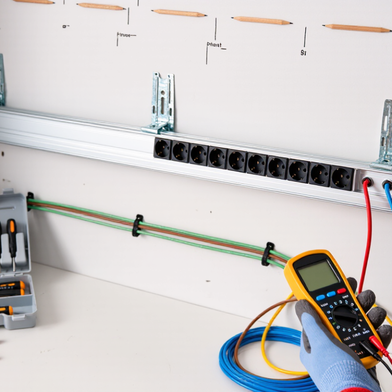
How to Install a Surface Power Track Safely?
A surface power track is an engineered distribution system, not a decorative rail. In my installations, I begin by matching the assembly with IEC 61534 requirements. Document its application, mounting method, environmental conditions, rated voltage, and rated current. Confirm its protection against electric shock. Check the current edition and national adoption. Standards evolve.
Under IEC 61534, verify the track’s rated voltage and current before selecting outlets or adapters. Compare them with the supply circuit, protective device, conductor size, and expected load. A 16 A track is not automatically suitable for a continuous 16 A load. Heat, grouping, ambient temperature, and connector resistance may reduce capacity. Calculate diversity honestly. IEC test conditions do not replace site verification. Check earth continuity, polarity, contact spacing, and mechanical locking with calibrated equipment.
The risk is measurable. The U.S. Bureau of Labor Statistics recorded 145 fatal occupational injuries involving electricity in 2022. That figure supports careful commissioning. Mount the track on a sound surface, isolate power during installation, and torque terminals correctly. Label the circuit clearly. I sometimes find drawings incomplete around future outlets. That weakness needs correction. Record voltage, insulation results, protective-device rating, and final connected load. Recheck after furniture moves or equipment is added. Small changes can defeat a correct calculation.
| Verification Dimension | Technical Requirement or Data | Safe Installation and Assessment Method | Acceptance Record |
|---|---|---|---|
| 1. Product Classification and Applicable Standard | |||
| Product family | Surface-mounted power track system, consisting of a track, conductors, accessory units, end components and mounting hardware. | Confirm that the complete system is designed and tested as one compatible assembly. Do not combine track sections and accessories from unrelated systems. | System identification and installation instructions recorded. |
| Primary standard | IEC 61534, Powertrack systems. | Use the current edition adopted by the authority having jurisdiction. Review the applicable general requirements and the relevant particular requirements for the intended installation. | Edition and national adoption verified. |
| Likely mounting category | For a track mounted on a wall or ceiling surface, assess the applicable IEC 61534 particular requirements for wall- and ceiling-mounted powertrack systems. | Check the manufacturer’s declared mounting method, orientation, permitted accessories, enclosure properties and installation limitations. A floor-mounted system may require different particular requirements. | Mounting category matches the product documentation. |
| Declared voltage and current | Example design data: 230 V AC, 16 A maximum track rating. | Use the lower of the track rating, accessory rating, protective-device rating, conductor rating and supply-circuit rating. The complete circuit must not be treated as 16 A unless every relevant component is rated accordingly. | Rated voltage and current shown on product marking or technical documentation. |
| System compatibility | Track, connectors, tap-off units, covers, end caps and protective earth components must be approved for use together. | Verify keying, polarity, earth continuity, mechanical engagement and the permitted number and type of accessory units. Never modify the track or bypass the protective earth. | Compatibility check completed. |
| 2. Site and Mounting Safety | |||
| Installation location | Dry indoor surface unless the product documentation specifically permits another environment. | Check ambient temperature, humidity, dust, water exposure, corrosive substances, impact risk and access for maintenance. Use an enclosure and accessories suitable for the environment. | Environmental suitability confirmed. |
| Substrate condition | Wall or ceiling must be structurally sound and capable of supporting the track and connected accessories. | Locate hidden cables and pipes before drilling. Select anchors and screws for the substrate type and expected mechanical loads. Do not rely on adhesive alone unless specifically approved. | Substrate and fixing method documented. |
| Mounting spacing | Use the spacing specified by the product installation instructions; no universal spacing value should be assumed. | Install every required support, particularly near joints, ends, bends and accessory points. Keep the track straight and prevent twisting or sagging. | Support spacing matches the installation instructions. |
| Mechanical protection | Track and accessories must be protected from foreseeable impact, crushing, excessive bending and unauthorized alteration. | Maintain required clearances from heat sources and moving equipment. Provide guards or a different mounting method where the track can be struck or exposed to water. | Protection measures recorded where required. |
| Isolation before work | Electrical work must be carried out on an isolated and secured circuit. | Switch off the supply, isolate all relevant sources, lock or label the isolator where practicable, and prove the tester before and after testing for absence of voltage. Installation and termination should be performed by a qualified person. | Isolation and safe-working procedure completed. |
| 3. Electrical Load-Rating Confirmation | |||
| Connected-load calculation | For single-phase AC: I = P ÷ (V × PF). | List each connected load, its rated power, quantity, supply voltage and power factor. For mixed loads, calculate each load separately and add the currents. | Load schedule prepared and retained. |
| Illustrative connected load | Example: 2,400 W total at 230 V and power factor 0.95. | I = 2,400 ÷ (230 × 0.95) = 10.99 A, rounded to 11.0 A. | Calculated load current: 11.0 A. |
| Track-current comparison | Example track rating: 16 A. Example calculated load: 11.0 A. | Nominal current margin = 16.0 A − 11.0 A = 5.0 A. This margin does not replace requirements for diversity, temperature correction, inrush current or local electrical rules. | Passes the basic example comparison only. |
| Protective-device coordination | Protective-device rating must not exceed the allowable rating of the weakest component in the circuit. | Check the upstream protective device, supply conductors, track conductors, tap-off units, plugs, sockets and connected equipment. Consider short-circuit rating and disconnection requirements. | Protection coordinated with the complete circuit. |
| Continuous or high-duty loads | Continuous operation, heating equipment, motors, LED drivers and power supplies may require additional design allowance. | Apply the design margin required by the applicable electrical code and the equipment manufacturer. Do not automatically use the full nameplate current for every operating condition or assume an 80% rule applies universally. | Duty cycle, inrush and design margin evaluated. |
| Simultaneous accessory loading | Total simultaneous current from all energized tap-off units must remain within the system and circuit limits. | Prevent overload caused by adding multiple accessories after installation. Clearly identify spare capacity and any restrictions on accessory quantity or placement. | Maximum simultaneous load stated on the handover record. |
| Mechanical load of accessories | Electrical current rating is different from the physical weight or pull-out rating of an accessory. | Use the declared mechanical load rating for each tap-off unit, adaptor, pendant or suspended fitting. Provide independent support where the accessory or luminaire weight exceeds the permitted track load. | Mechanical and electrical ratings checked separately. |
| 4. Installation Sequence and Inspection | |||
| 1. Plan the route | Route avoids heat, water, impact zones and inaccessible service areas. | Mark the track line, accessory locations, supply point and support locations. Confirm that the finished installation will remain accessible for inspection and maintenance. | Layout approved before drilling. |
| 2. Install supports | Supports, screws and anchors are suitable for the substrate and product instructions. | Install supports level and aligned. Do not drill, cut or alter current-carrying parts unless the system instructions explicitly permit the operation. | Fixings visually inspected and tightened. |
| 3. Install and join track sections | Joints are fully engaged, correctly oriented and protected by the specified covers or connectors. | Check conductor alignment, polarity, joint covers and earth continuity provisions. Keep unused openings closed with approved components. | All joints and covers secure. |
| 4. Connect the supply | Supply conductors are correctly identified, terminated and protected against strain. | Connect line, neutral and protective earth according to the wiring diagram. Tighten terminals to the specified torque and ensure no exposed copper is left outside the terminal. | Terminal torque and conductor identification recorded. |
| 5. Fit accessories | Accessories are fully inserted, locked and correctly polarized. | Use only compatible tap-off units. Confirm that earth contacts engage before or together with live contacts where required by the product design. Do not force or rotate an incompatible accessory. | Accessory engagement and locking verified. |
| 5. Commissioning and Handover Tests | |||
| Visual inspection | No cracks, exposed conductors, loose covers, sharp edges, deformation or unsupported sections. | Inspect the complete route, joints, ends, accessories, labels, supports and enclosure condition before energizing. | Visual inspection passed. |
| Protective earth continuity | All exposed conductive parts and protective-earth paths are continuous. | Test with suitable calibrated equipment using the method required by the applicable electrical code and installation standard. Record measured results. | Measured value and test instrument recorded. |
| Insulation resistance | Insulation resistance must meet the applicable installation-standard limit for the circuit and equipment. | Test only after confirming that connected electronic equipment and surge-sensitive devices will not be damaged by the selected test voltage. Isolate or disconnect equipment when required. | Test voltage, measured value and conditions recorded. |
| Polarity and conductor verification | Line, neutral and protective earth are correctly connected throughout the system. | Verify polarity at the supply and at each relevant outlet or tap-off point. Confirm that switching and protective devices interrupt the intended conductors. | Polarity and conductor checks passed. |
| Residual-current protection | Where required by the applicable electrical code, the circuit is protected by a suitable residual-current device. | Verify device type, rated residual operating current, compatibility with connected loads and test-button operation. Follow the local code for required protection levels. | Protection type and functional test recorded. |
| Functional and load test | Track operates without overheating, nuisance tripping, arcing, abnormal noise or loose accessories. | energize only after dead tests pass. Operate connected loads under representative conditions and inspect terminals, joints and accessories for abnormal temperature rise. | Functional test completed without abnormal conditions. |
| Documentation and warning label | Final circuit rating, maximum permitted load, compatible accessories and isolation point are identified. | Provide the load schedule, test results, installation instructions, maintenance information and any restrictions on future additions. | Handover pack completed. |
Confirm the track’s rated voltage and current under the applicable installation standard. Compare them with the supply voltage, circuit breaker, conductor size, and expected load. A 16 A rating does not guarantee a continuous 16 A load. Heat, grouping, ambient temperature, and connector resistance can reduce capacity.
Identify the correct circuit at the distribution board. Switch off the breaker and prevent accidental re-energizing. Lock or supervise the breaker during work. A warning note alone is insufficient. Stop there if isolation is uncertain.
Use a properly rated CAT III 600 V meter with undamaged leads. Test it on a known live source before testing the track. Check line, neutral, and protective earth for zero voltage. Test the meter again afterward. This live-dead-live method confirms the meter worked throughout.
Follow the specified fixing points, spacing, and clearances. Measure the wall before drilling. Keep the track level and firmly supported. Use suitable anchors for hollow walls and correctly sized fixings for masonry. Extra support may be needed near joints, corners, or heavy accessories.
No. A 30 mA RCD provides additional protection where local rules require it. It does not replace protective earthing, polarity checks, or suitable overcurrent protection. Press its test button after installation. Then verify the circuit using calibrated instruments.
Look for crushed cables, exposed conductors, damaged insulation, and loose terminals. Check that mechanical parts lock correctly. A loose terminal may heat slowly without obvious warning. Small errors matter. I sometimes underestimate alignment problems until repeated use reveals them.
Record the measured voltage, insulation results, protective-device rating, and final connected load. Check earth continuity, polarity, contact spacing, and terminal torque. Use calibrated equipment where required. Incomplete drawings can hide future outlet changes. That weakness needs correction.
Recheck it after furniture moves or new equipment is connected. Recalculate the expected load when accessories change. Inspect for sagging, stressed connections, or altered clearances. A correct calculation can become outdated. Standards and site conditions change.
Learning how to install a surface power track safely begins with identifying the system under IEC 61534 and confirming that its rated load matches the intended application. Before any work, map the circuit for the correct 120 or 230 V supply and ensure suitable 15–20 A overcurrent protection is provided. Disconnect the power at the appropriate isolation point, secure it against reconnection, and verify zero voltage with a properly rated CAT III 600 V meter.
Mount the track according to the manufacturer’s required spacing and environmental instructions, including protection by a 30 mA RCD where applicable. After installation, test polarity, protective-earth continuity, insulation condition, and the connected load before energizing the circuit. A controlled functional check can then confirm that the track and accessories operate correctly without excessive heating or abnormal noise. Because electrical work can be hazardous, installation, testing, and any corrective work should be completed or supervised by a suitably qualified person.

 Ranko Power